Tag: RV Hugh R Sharp

Demobilization and Remobilization of the Hugh R Sharp

Summer is an especially busy time for research vessels. The UNOLS fleet is making increasing use of containerized portable lab vans to shave some time and effort off of offloading the science party from one cruise and loading up the next mission and their gear. They also increase the flexibility of the research vessels by giving them the option to add additional science capabilities and facilities to vessel users. Options include adding:

  • Dry Labs
  • Wet Labs
  • Isotope Labs
  • Clean Labs
  • Cold Labs
  • Additional Berthing

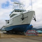
This is a time lapse that we shot of the RV Hugh R Sharp returning from a multi-week scallop survey, unloading one lab van and then loading two more fresh ones before fueling up (both diesel and food) and departing on the next mission. Enjoy!

3DVista Panoramic Tour of the Sharp

I tinkered around with a demo copy of the 3DVista Stitcher and 3DVista Show 3.0 to push its capabilities a tad. I touched on the packages in a previous blog post about the Global Visualization Lab where I did a simple panorama of the room. The wheels started turning and we decided to push the envelope a little and create a series of panoramic views of the RV Hugh R Sharp as a proof of concept for an online virtual tour of a research vessel.
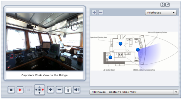
Panoramic Tour of the RV Hugh R Sharp

Click on this image to visit the proof-of-concept panorama…

The image above is a screen shot of the proof-of-concept panoramic tour we came up with. Click the image above or this hyperlink to visit the actual panoramic tour. The pane on the left shows an interactive panorama of the various points of interest on the ship. The right-hand pane shows a scan of the deck and compartment that the panorama represents. If there is no user action, the tour will cycle through a complete 360 view of each panorama and will move onto the next panorama in the list if nothing is clicked. There are two drop-d0wns to the right, one above the deck layout to select a specific panorama and one below it to select a specific panorama.

A really cool feature of the product is the ability to take the panorama full-screen for a more immersive experience. To do so, just click on the arrow button in the top-right-hand corner next to the question mark symbol. Once in full-screen mode, you can easily cycle through the various pano’s by mousing over them near the bottom of the screen.

The 3DVista Show software allows you to insert hot-spots into the panorama’s as well that can either link to other pages/sites or to include an audio clip into the mix. This makes it quite easy to include additional information about a specific area or feature. I inserted an animated arrow pointing to the Multibeam Operator Station on the Main Deck -> Multibeam Tech Area that links out to the Reson Seabat 8101 Multibeam Echosounder posting.
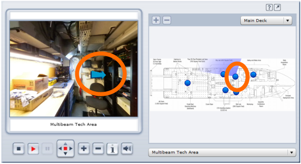
Multibeam Tech Pano

The mind races with the various uses for this type of technology. It allows for mobility impaired individuals and class groups to tour a space that they’d ordinarily be unable to access. It also allows scientists to “look around” and get a feel for the spaces that they’d be using when they come onboard a vessel. For a future project, I’d like to get support do some panorama’s both inside and outside of the various UNOLS lab vans that would allow scientists to virtually stand in the lab vans and walk around them to see how they’re laid out. 3D panorama’s of research sites in remote locations like the arctic and antarctic also come to mind as does tours of mineral sample and other collections with hotspots included for the various specimens for links to additional information. The application of this tech abounds.

I talked with the folks at 3DVista and it looks like they offer a 15% academic discount for the software so be sure to ask about if if you’re going to purchase it. They also list a one-shot 360 degree pano lens and adapters to make shooting the digital pics a little easier. We used a 180 degree fish-eye lens for our pano shots, which means we did 3 shots at each location 120 degrees off from one-another and stitched them together with the 3DVista Stitcher program.

Many thanks to Lisa Tossey for taking the photos and getting this project rolling. I posted this as an unpolished proof-of-concept version. I look for the ready-for-prime-time panorama that she comes up with for the CEOE site. I also look forward to seeing any cool panoramas that are out there for research projects. Be sure to share your links.

Video Tour of the Research Vessel Hugh R Sharp

RV Hugh R Sharp ready for launchWe recently had guests come down to take a tour of the Lewes campus and the Research Vessel Hugh R Sharp. One of the guests was wheelchair-bound and was limited to only seeing the main deck of the ship as getting to the rest of the ship would have required going up and down stairs. The Sharp has accommodations for handicapped scientists, but they are pretty much limited to the main deck. This limits their access to just the aft working deck, the wet and dry labs, the galley and the conference room. The wheels started turning during that tour on how to share the rest of the technological awesomeness of the Sharp with others. I decided to take my trusty $100 video camera in hand and record a video tour of the ship for those that are unable to navigate the stairs, and for classrooms and visitors who just can’t make the trek to Lewes for a tour. It’s a tad long, running just over 40 minutes or so, but it covers almost the entire ship. Enjoy!

Many thanks to Captain Jimmy Warrington for taking time to do a whirlwind tour just prior to a science mission – as you can tell from the video, he’s a natural at relaying information about the RV Hugh R Sharp and its science capabilities.

Detailed drawings showing deck layouts and profiles of the Sharp can be found the RV Hugh R Sharp landing page, which includes PDFs of:

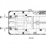
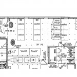
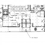
To help you orient yourself a little bit as to the spaces that were covered, here are some deck diagrams to show the overview of a few of the spaces.

SHARP-AftDeck

Aft Deck

SHARP-DryLab

Dry Lab

SHARP-WetLab

Wet Lab

Caley Ocean Systems CTD Handling System


One of the interesting innovations on the RV Hugh R Sharp is the incorporation of a “CTD Handling System” from Caley Ocean Systems. The video above was taken from the wet lab of a CTD Rosette being deployed and recovered using this system. If you search around on YouTube, you can find some interesting videos of crews deploying and recovering the CTD Rosette system. What you typically find is that you have one crane operator and then two or three crew members on deck with poles and/or ropes to try and guide the CTD back onto the deck. With the ship rocking and rolling out to sea, this can be a tad dangerous, especially when much of this work is done close to the waterline with waves splashing on deck.

The RV Hugh R Sharp has a CTD handling system that is pretty much designed to be operated by one marine technician, one of two currently in use in the UNOLS fleet (the other is on the RV Kilo Moana).

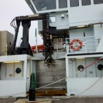
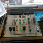
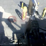
The marine technician on the Sharp is up on the bridge level and looks down through windows at the wet lab area and beside the ship. This allows them to control the deployment and the recovery of the CTD from a much safer location. The Caley CTD Handling System has motion compensation built in to cancel out the roll and pitch of the ship and is designed to mostly eliminate the swaying of the CTD system.  This makes for a much smoother and safer CTD deployment and recovery, which can occur quite often on many research vessels. The following pictures show the control station up on the bridge and an exterior view of the Caley CTD Handling System onboard the Sharp.

Caley Ocean Systems CTD Handling System - RV Hugh R SharpCTD Handling System Control Station - RV Hugh R SharpView From The Control Station

Next time I’m out on the Sharp, I’ll try to get a view of the system in action from outside the wet lab.

Is the system perfect? No, they still have some kinks to work out and with Caley located over in the UK, turn-around time can be pretty slow at times. The vessel operators are taking some lumps and trying to iron the kinks out of a system that can help make it a little safer to do routine underway CTD casts. Their efforts should be applauded.

CTD and Dissolved Oxygen Measurement via Winkler Titration

Last fall I was on the RV Hugh R Sharp for a short research cruise out in the Delaware Bay. We were sharing the Sharp with chief scientist Dr. George Luther, who was doing a mooring deployment that contained a dissolved oxygen sensor (among several other sensors). As part of the calibration check to make sure the readings were correct while we were on station, Dr. Luther did several CTD casts to take some water samples at various depths. I snagged the trusty video camera and got him to explain what he was doing and why.

To verify the accuracy of modern electronic oxygen sensors, oceanographers still verify the dissolved oxygen concentration using what’s called the Winkler test for dissolved oxygen. Dr. Luther showed the process of fixing oxygen into a MnOOH solid, which is then measured by the Winkler titration. This allows scientists to compare the oxygen readings they’re getting now with historical records of oxygen levels going back to the late 1800’s (an important thing to do when you’re trying to determine long-term trends by comparing historical records against more recent observations). It also allows them to verify the readings that they’re getting from modern electronic oxygen sensors.

I’ll sneak down to Dr. Luther’s lab soon and video the second part of the process, where they add the additional chemicals to the mix and determine the actual concentration of dissolved oxygen. Thanks again to Dr. Luther for taking time to explain the process.

Reson Seabat 8101 Multibeam Echosounder

I lucked out not too long ago and happened to be at the right place at the right time (usually it’s the other way around). I ran into Brian Kidd, our resident expert on Multibeam Echosounder systems (also known as a Swath system) and he said he just happened to have the multibeam components apart for servicing.  I ran to get my camera and followed Brian around and asked all kinds of insightful questions (of course).  Echosounders are a version of Sonar (which stands for SOund Navigation And Ranging) wherein a transmitter emits a sound pulse downward into the water and then the amount of time that the pulse takes to come back to the ship is measured. A single beam echosounder will shoot a beam straight down and and use a single receiver to receive the pulse that bounced back from the bottom of the body of water. This is used to determine how deep the water is beneath the ship. A multibeam echsounder will emit a broad pulse of sound into the water and then will use multiple receivers aimed at various angles to measure the reflected sound.  These times are then processed by the computer to generate a “swath” beneath the ship and at some distance to either side which shows the height of the sea floor.  Moving the ship forward will give a band of height information beneath the ships track, and by moving in parallel, overlapping tracks, an ever-growing patch of sea floor heights can be mapped.

Okay, I’ve exhausted my general knowledge of the subject.  I’ll let Brian take the reigns and kick back and learn from the master…


At the 2009 RVTEC meeting, I sat in on the Swath/Multibeam workshop and updated the Swath/Multibeam section of OCEANIC’s International Research Vessels database for the UNOLS vessels. There were some huge swath transducer arrays being discussed at the workshop on some of the deep water vessels, so I was pretty surprised to see just how compact the shallow water multibeam systems can be. In the second part of the video, Brian shows us what the Reson Seabat 8101 transducer assembly looks like and how they mount the unit to the ship.


Many thanks to Brian for putting up with me and for taking time to share his knowledge of the Reson Seabat 8101 Multibeam System (PDF of specs here) onboard the RV Hugh R. Sharp.

Why two videos and not one? Apparently YouTube has a 10 minute max length for uploaded videos, so I broke the video into two parts.  Part 1 covers the monitoring and display station and Part 2 covers the mounting infrastructure and the transducer assembly. This works well for me as I doubt that too many people are able to sit through a 20+ minute video anyways, so breaking it up into two more digestible chunks is better in my opinion.

© 2024 Ocean Bytes Blog

Theme by Anders NorenUp ↑