Tag: NOAA

Predicting Sea Surface Salinity from Space

The simplest definition of salinity is how salty the ocean is. Easy enough, right? Why is this basic property of the ocean so important to oceanographers? Well, along with the temperature of the water, the salinity determines how dense it is. The density of the water factors into how it circulates and mixes…or doesn’t mix. Mixing distributes nutrients allowing phytoplankton (and the rest of the food web) to thrive. Globally, salinity affects ocean circulation and can help us understand the planet’s water cycle. Global ocean circulation distributes heat around the planet which affects the climate. Climate change is important to oceanographers; therefore, salinity is important to oceanographers.

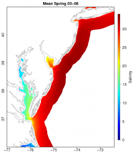
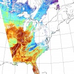
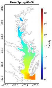
Spring Salinity Climatology for the Chesapeake

Spring Salinity Climatology for the Chesapeake

Salinity doesn’t vary that much in the open ocean, but it has a wide range in the coastal ocean. The coast is where fresh water from rivers and salt water in the ocean mix. Measurements of salinity along the coast help us understand the complex mixing between fresh and salty water and how this affects the local biology, physics, and chemistry of the seawater. However, the scope of our measurements is very small. Salinity data is collected by instruments on ships, moorings, and more recently underwater vehicles such as gliders. While these measurements are trusted to be very accurate, their spatial and temporal resolution leaves much to be desired when compared to say daily sea surface temperature estimated from a satellite in space.

So, why can’t we just measure salinity from a satellite?Well, it’s not as simple, but it is possible. NASA’s Aquarius mission http://aquarius.nasa.gov/ which was launched this past August is taking advantage of a set of three advanced radiometers that are sensitive to salinity (1.413 GHz; L-band) and a scatterometer that corrects for the ocean’s surface roughness. With this they plan on measuring global salinity with a relative accuracy of 0.2 psu and a resolution of 150 km. This will provide a tremendous amount of insight on global ocean circulation, the water cycle, and climate change. This is great new for understanding global salinity changes. What about coastal salinity? What if I wanted to know the salinity in the Chesapeake Bay? That’s much smaller than 150 km.

That’s where my project comes in. It involves NASA’s MODIS-Aqua satellite (conveniently already in orbit: http://modis.gsfc.nasa.gov/), ocean color, and a basic understanding of the hydrography of the coastal Mid-Atlantic Ocean. Here’s how it works: we already know a few things about the color of the ocean, that is, the sunlight reflecting back from the ocean measured by the MODIS-Aqua satellite. We know enough that we can estimate the concentration of the photosynthetic pigment chlorophyll-a. So not only can we see temperature from space, but we can estimate chlorophyll-a concentrations too! Anyway, there are other things in the water that absorb light besides phytoplankton and alter the colors we measure from a satellite.

Spring Salinity Climatology for the Mid-Atlantic

Spring Salinity Climatology for the Mid-Atlantic

We group these other things into a category called colored dissolved organic material or CDOM. CDOM is non-living detritus in the water that either washes off from land or is generated biologically. It absorbs light in the ultraviolet and blue wavelengths, so it’s detectable from satellites. In coastal areas especially, its main source of production is runoff from land. So, CDOM originates from land and we can see a signal of it from satellites that measure color. What’s that have to do with salinity?

You may have already guessed it, but water from land is fresh. So, water in the coastal ocean that is high in CDOM should be fresher than surrounding low CDOM water. Now we have a basic understanding of the hydrography of the coastal Mid-Atlantic Ocean, how it relates to ocean color, and why we need the MODIS-Aqua satellite to measure it. So, I compiled a lot of salinity data from ships (over 2 million data points) in the Mid-Atlantic coastal region (Chesapeake, Delaware, and Hudson estuaries) and matched it with satellite data from the MODIS-Aqua satellite in space and time. Now I have a dataset that contains ocean color and salinity. Using a non-linear fitting technique, I produced an algorithm that can predict what the salinity of the water should be given a certain spectral reflectance. I made a few of these algorithms in the Mid-Atlantic, one specifically for the Chesapeake Bay. It has an error of ±1.72 psu and a resolution of 1 km. This isn’t too bad considering the range in salinity in the Chesapeake is from 0-35 psu, but of course there’s always room for improvement. Even so, this is an important first step for coastal remote sensing of salinity. An algorithm like this can be used to estimate salinity data on the same time and space scale as sea surface temperature. That’s pretty useful. The folks over at the NOAA coastwatch east coast node thought so too. They took my model for the Chesapeake Bay and are now producing experimental near-real time salinity images for the area. The images can be found here: http://coastwatch.chesapeakebay.noaa.gov/cb_salinity.html. They will test the algorithm to see if it is something they want to use

Climatologies of salinity for all of my models can be downloaded here: http://modata.ceoe.udel.edu/dev/egeiger/salinity_climatologies/.

I view this project as an overall support of the NASA Aquarius mission by providing high resolution coastal salinity estimates that are rooted in in situ observations. I hope this information proves to be useful for coastal ocean modeling and understanding the complex process that effect the important resource that is our coasts.

Hurricane Katia Footprints

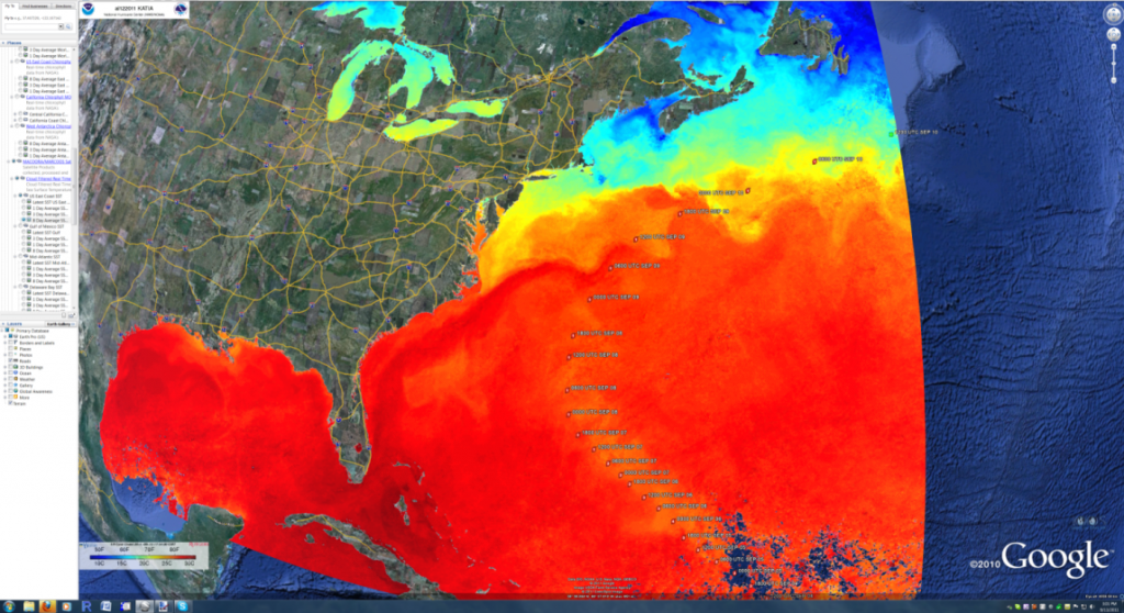
The ORB Lab was having a meeting in the GVis Lab this week and, as usual, the East Coast US 8-Day Averaged Sea Surface Temperature overlay was up on the screens. Dr. Oliver pointed to the screen and noted that there was a path cutting across the Gulf Stream that was cooler than usual and that it was probably due to upwelling and mixing from hurricane Katia. Sure enough, we loaded up a layer showing Katia’s track and they lined up.

Katia SST Trail

Katia SST Trail

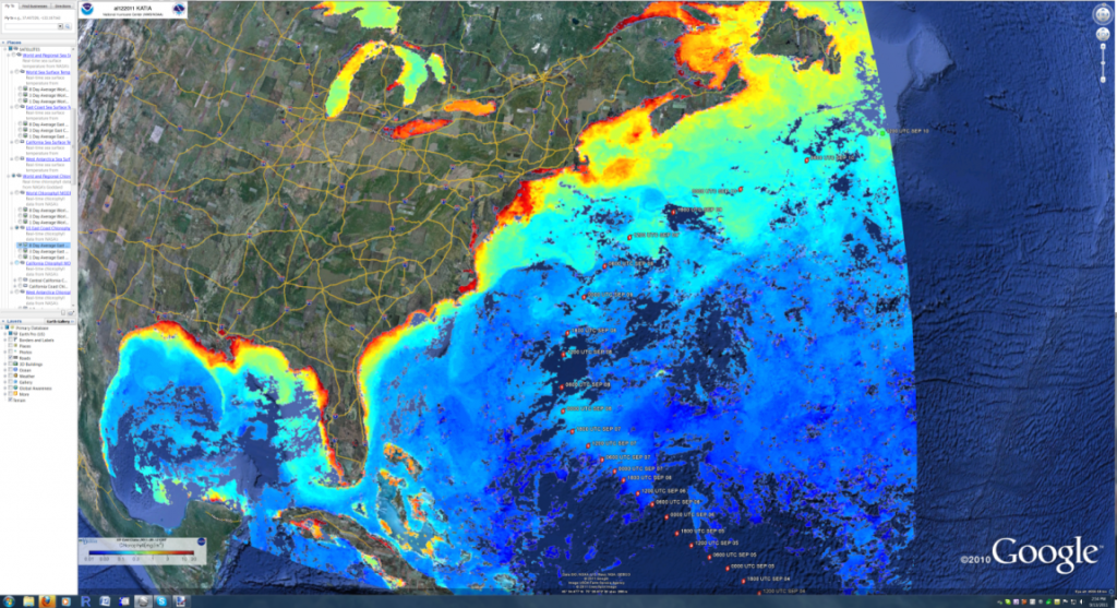
We then checked to see if there was anything noticeable on the East Coast US 8-Day Average Chlorophyll layer and you can see what appears to be a slight bloom in chlorophyll along the track as well (slightly lighter blue).

Katia Cholorophyll Trail

Katia Cholorophyll Trail

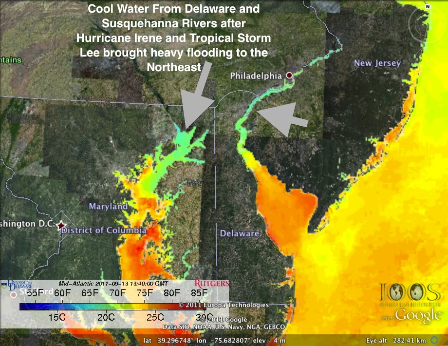
Another neat view is the markedly cooler water that you flowing into the bays from the increased river discharge that resulted from the large amounts of rain dropped by hurricane Katia and tropical storm Lee as they passed through.

Cold river water 20110913

Cold river water 20110913

These layers and several others are processed and uploaded daily and made available via the Orb Lab website in the Public Access section. They are exposed via Google Maps interfaces as well as Google Earth embedded views and linkable KMZ file formats. Neat stuff!

Polar Orbiting Satellite Receiving Station

The video above is a quick screencast NASA JPL’s Eyes on the Earth application, which shows the tracks of various satellites orbiting the globe. It’s a really cool application that gives a top-notch overview of some of the satellites currently in orbit and their trajectories around the Earth. Take some time and poke around, you’ll be glad you did.

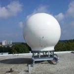
Polar Satellite RadomeThe reason I included it is that I promised to cover the polar orbiting satellite receiving station in a previous blog post about the new Satellite Receiving Station in Delaware. In the previous post I discussed the geostationary satellite receiving station. In this post, I hope to shed some light on the polar orbiting receiving setup.

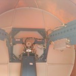
What’s Inside the Radome

MODIS Satellite PassThe equipment for the polar orbiting satellite receiving station is a bit more involved than the pretty much non-moving geostationary setup. As the name implies, the polar orbiting satellites do just that, they orbit the Earth north and south, going from pole to pole. Their path is relatively simple, they just go around the earth in circles, but as they’re doing so, the Earth is rotating beneath them. The satellites point their cameras towards the earth and essentially capture a swath of data during each rotation. Since the Earth is rotating beneath them, the swath appears as a diagonal path if you look at the overlay.

Inside the RadomeIn order to capture data from a moving target, the dish has to be able to rotate and move in three axis in order to follow the satellite of interest. In order to protect the receiving equipment from the weather, it is typically installed in a circular fiberglass enclosure called a “radome”. To keep the design relatively simple, there is only one mounting configuration and radome setup created, and that’s designed to mount onboard a ship. It is then relatively simple to attach a mounting bracket to the top of a building and bolt the radome assemgly to it.

The video at the top of the page shows that there are several satellites in orbit, so the Terascan software has to pull down satellite ephemeral data from Celestrak each day, take into account the location of the tracking station, and generate a calculated schedule of which satellites will be visible to the satellite dish throughout the day. As there may be more than one satellite in view during any given time period, the satellite operator assigns a priority weighting to each satellite. The Terascan software then uses that weighting to decide which satellite it will aim the dish at and start capturing data.

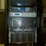
Receiving Station Workstations

Acquisition and Processing SystemsInside the building is a rack of computers and receivers whose purpose in life is to control the dish on the roof of the building and to receive and process the data it relays down from the satellite. The receiving station at UD has both X and L-Band receivers which receive the data stream and pass it to a SeaSpace Satellite Acquisition Processor. The processor then sends the data packets to a Rapid Modis Processing System (RaMPS) which combines the granularized HDF data files from the satellites into a TeraScan Data File (TDF) file. Once in this format, various programs and algorithms can be run against the TDF file and channels of interest can be combined using NASA/NOAA and other user supplied algorithms to create the output product of interest. As the files can get rather large and there can be several of them coming in throughout the day, they are then moved over to a Networked Attached Storage (NAS) server and stored until they are needed.

Satellites Licensed

The UD receiving station is licensed and configured to receive data from the following satellites:

  • Aqua
  • Terra
  • NOAA 15
  • NOAA 17
  • NOAA 18
  • NOAA 19
  • MetOp-A (Europe)
  • FY-1D (China)

Hopefully this sheds a little more light on the polar orbiting receiving station and its capabilities. Let me know if there are any additions or corrections to the information I’ve posted.

New Polar and Geosynchronous Satellite Receivers for Delaware

A few weeks ago they fired up a new satellite receiving station from SeaSpace at the University of Delaware’s main campus in Newark, DE. Two receivers were brought online, one for L-Band reception from Geosynchronous Satellites and one for X/L-band reception from Polar Orbiting Satellites. Both receiving systems have dishes that are mounted on the roof of Willard Hall as it presented the least obstructed view of the sky. The adds additional capability to an east coast satellite operations contingent which includes:

  • University of Maine
  • City College of New York
  • Rutgers University
  • University of Delaware
  • University of South Florida
  • Louisiana State University
  • Purdue University

For this blog posting, I’ll only cover the geosynchronous satellite capabilities. In a future posting I’ll cover the polar orbiting hardware and its capabilities.

Geosynchronous Satellite

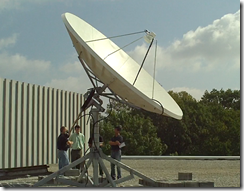
UD Geosynchronous Satellite Dish

The beauty of geosynchronous satellites is the simplicity with which they can be tracked. Rather than flitting all about and requiring fancy calculations and equipment to track them, you merely point the dish to a point in the sky where the satellite remains fixed relative to the motion of the earth and pretty much lock the receiving dish down. Since the satellite is moving with a trajectory and speed that matches the rotation of the earth, the satellite is said to be “geo-stationary”.

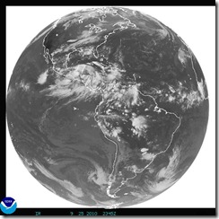
The dish used to receive the signals from the geosynchronous satellites is therefore simple in its design. It is mounted with only one axis of movement, meaning it can only be adjusted along an arc of the sky either to the east or to the west. There is a motor and lead screw mounted on the back that will either push the dish one way, or pull the dish the other in order to position it for the best signal strength. The current intent of the UD dish seems to be dedicated to constantly receiving real-time data from the GOES-EAST satellite (also known as “GOES-13”). GOES East outputs full disk imagery of the the earth from a longitude of 75 degrees west, which gives a good view of pretty much all of North and South America and a good chunk of the Pacific and Atlantic Ocean.

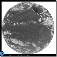
GOES stands for “Geostationary Operational Environmental Satellite” and it is operated by NOAA’s NESDIS or “National Environmental Satellite, Data, and Information Service” primarily to support meteorological operations and research, which includes weather forecasting and storm tracking. The dish is oriented in such a way that it could also be programmed to point to GOES-WEST (aka GOES-11)  for a satellite view of the Pacific Ocean (centered around 135 degrees west longitude) as well if the need arises.

GOES East Full Disk Infrared GOES West Full Disk Infrared

GOES Sensors

One thing to bear in mind is that GOES-13 hasn’t always been “GOES East” – it took over for GOES-12 in April 2010, with GOES-12 moving to 60 degrees West to replace GOES-10 (decommissioned) for coverage of South America. I note this so that you don’t assume that the sensors (and/or their calibration factors)  for a particular GOES station are always the same.

Imager

The current GOES-East has optical imagers with 6 channels with resolutions of 1.1km for the visible channel (one); and 4km and 8km resolutions for the near infrared, water vapor and thermal infrared channels (two through six). The imager is basically a rotating mirror and lens configuration that scans the earth from north to south, line by line to receive reflected visible light, water vapor as well as infrared radiation channels. Each line scanned is digitized and transmitted back towards the earth with measurement units of percent albedo for visible light and temperature for the water vapor and infrared information. Spectral response functions can now also be downloaded online from the NOAA Office of Satellite Operations as well as other GOES calibration information.

Sounder

GOES satellites are also equipped with a sounder with 8km resolution. The sounder scans the atmosphere over the land and ocean and provides vertical profiles which include the temperature of the surface and cloud tops as well as derived wind velocities from these measurements.

Real-time Access to Data

The key feature to having a satellite receiving station on-site is the access to the raw, real-time satellite data. Sure, you can get pull some images down from the NOAA Geostationary Satellite Server, but they would be just derived images. Scientists here at UD and elsewhere are interested in getting the latest raw data feeds from the satellites so that they can research and develop algorithms that process the raw channel data into other products in support of their research projects.

Next on my agenda is to try to give some insight into the polar orbiting satellite tracking station and the fancy gear that sits inside the radome enclosure. Cheers!

© 2025 Ocean Bytes Blog

Theme by Anders NorenUp ↑