Tag: CEOE

Atlantic sturgeon arriving earlier in the mid-Atlantic

The unusually warm conditions in the winter and spring of 2012 have resulted in water temperatures up to 3°C warmer than the previous 3 years resulting in comparable Atlantic sturgeon catches off the coast of Delaware occurring 3 weeks earlier than past sampling efforts.  During sampling events for Atlantic sturgeon we have also documented sand tiger sharks arriving off the coast of Delaware in late-March, a full month earlier than documented in previous seasons.

My research, conducted jointly with Dewayne Fox at Delaware State University and Matt Oliver at the University of Delaware, is focused on coastal movements and habitat use of adult Atlantic sturgeon during the marine phase of their life history.  By utilizing acoustic biotelemetry on both traditional fixed array platforms as well as developing mobile array platforms coupled with Mid-Atlantic Regional Association for Coastal Ocean Observing Systems (MARACOOS) I am going to model Atlantic sturgeon distributions in a dynamic coastal marine environment.  This research is particularly relevant given the recent protection of Atlantic sturgeon under the Endangered Species Act.  Determining factors influencing Atlantic sturgeon movements and distributions during their marine migrations will enable dynamic management strategies to reduce mortalities as well as impacts to commercial fisheries, dredging efforts, and vessel traffic.  In addition to allowing for dynamic management strategies the development of models for adult Atlantic sturgeon movements and distributions in relation to dynamic environmental conditions will illustrate how changing environmental conditions are going to impact this Endangered Species moving forward.

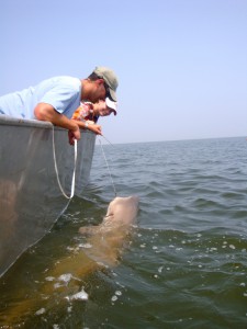
Graduate student Matt Breece with a recently telemetered female Atlantic sturgeon off the coast of Delaware

Utilizing New Tagging Technology to Characterize Sand Tiger Shark Habitat

Sand tiger sharks are large bottom dwelling sharks found in the coastal waters of the Eastern North Atlantic, and are known to frequent the Delaware Bay in the summer months. Sand tiger shark populations are currently in danger of over exploitation because they are slow growing and have extremely low birth rates. While we know that the sharks are found within the Delaware Bay during summer months, little is known about their movements during the rest of the year, or what oceanographic conditions limit their spatial extent. There is evidence that these sharks make large coastal migratory movements along the Eastern Seaboard. This makes habitat characterization difficult because the sharks travel throughout such a large area. It is important for managers to know the areas of intensive use by the sharks, and the species assemblages within those areas, in order to protect these apex predators.

Dr. Matthew Oliver and Danielle Haulsee with a sand tiger shark caught in the Delaware Bay.

Our project, a collaboration among Delaware State University’s Dewayne Fox and the University of Delaware’s Matthew Oliver and Danielle Haulsee, will document and characterize the movements of sand tiger sharks, their habitat preferences, and the community assemblages they encounter using new and innovative electronic tagging technology. Sand tiger shark movements will be recorded using passive telemetry in addition to pop-off satellite archival tags. We will also deploy a new type of tagging technology, which acts as a mobile receiver, and will record any encounters with other sharks, fish or other marine animals that have been tagged with acoustic tags. We will then use satellite and remotely sensed data resources from the Mid-Atlantic Regional Association for Coastal Ocean Observing Systems (MARACOOS) to characterize and model the habitats and oceanographic conditions used by sand tiger sharks. This study will give managers a better understanding of the spatiotemporal patterns in sand tiger shark movements along the East Coast, as well as inform management decisions regarding sand tiger shark habitat utilization.

Conch Reef Survey for NASA’s NEEMO 15 Project

Dr. Art Trembanis’ Coastal Sediments, Hydrodynamics & Engineering Lab (CSHEL) has been pretty busy lately. Not long ago I did a post about the prototype sub-bottom profiler section that he added to his Autonomous Underwater Vehicle (AUV) (see: Sub-Bottom Profiling using an AUV). I was down at the NASATweetup for the Endeavour (STS-134) launch not long ago and I got chatting with some folks from NASA’s Open Goverment Initative about the NEEMO 15 project (NEEMO stands for “NASA Extreme Environment Mission Operations“) and we discussed UD’s involvement.

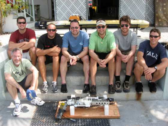
It takes a village of roboticists to run a successful AUV campaign

It takes a village of roboticists to run a successful AUV campaign

When I emailed Dr. Trembanis upon my return to Delaware, he emailed me back with instructions to browse to UNCW’s Life Support Buoy live webcam above the Aquarius Reef Base. Sure enough, he was there aboard the RV George F. Bond monitoring his Gavia Scientific AUV as it acoustically mapped the Conch Reef around the Aquarius as a precursor robotic mission for NEEMO 15.

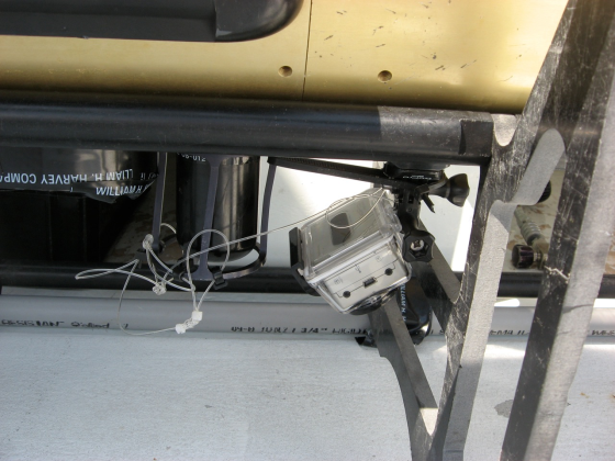
Go Pro Hero Attached to the AUV

Go Pro Hero Attached to the AUV

Here is video footage shot by an off-the-shelf HD Go Pro Hero digital video camera that was attached to the AUV:

httpv://www.youtube.com/watch?v=8n3nR9TaVGo

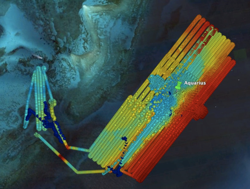
The mapping mission ran for 4 days and covered approximately 100km, resulting in about 15Gigabytes of raw data. Here’s an overview map of the mission.

Aquarius NEEMO 15 precursor survey

Aquarius NEEMO 15 precursor survey

Many thanks to Dr. Trembanis for the video and imagery to go along with the story. Be sure to visit NASA’s NEEMO site to learn more about the mission and what’s to come. Visit the CSHEL site to learn more about the research that’s going on there and to see other cool video and image products that they’re producing.

Outdoor Webcam 101

Some time ago I was asked what would it take to get a live webcam feed of the osprey nest next to our Marine Operations Building. We have an osprey couple – Ricky & Lucy – and people love to check in on them throughout the summer months when they come home to Lewes.
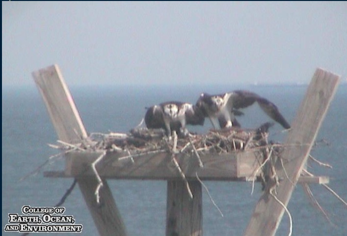
Ricky & Lucy
Ricky & Lucy

I thought I’d share the software and hardware lineup that I selected to do the job and explain some of my choices. The equipment I ended up ordering was:

  • Sony SNC-RZ30N PTZ (pan + tilt + zoom) IP Webcam (~$1,100)
  • Dotworkz D2 Outdoor Enclosure with heater/blower (~$500)
  • Videolarm APM3 Pole Mount Bracket (PDF) (~$60)
  • WebcamXP network camera monitoring, streaming & recording software (~$99)
  • Some sort of intermediary computer to run the WebcamXP software
  • 100′ Outdoor Extension/Power Cord
  • 100′ Underground Double-shielded Cat5 Network Cable
  • Uninterruptable Power Supply (UPS)
  • Desiccant packs, Velcro Tape & a Plastic Container
  • RainX and Marine Silicone RTV

Why I picked what I did

We wanted to mount the webcam on an existing antenna tower next to the Marine Operations Building, thus the pole mount bracket. The webcam needed to have a short shopping list of features – including:

  • Stand-alone operation and a physical network jack for IP (network) streaming – we didn’t want to potentially impact building wifi performance and we just wanted to be able to run a network line up to it (no USB webcams need apply). Doing this with a network cable tied into our building switch meant that the packets the camera generated would not negatively impact the rest of the users.
  • It needed to have sufficient intelligence that we could remotely log into it to position it and/or program preset camera stops and zoom factors.
  • A healthy optical zoom so we could zoom up close on the nest for an up-close experience.
  • Image stabilization built-in so that when we did zoom in, any sway or vibration in the antenna pole wouldn’t give us a jittery image.
  • FTP/FTPS functionality – where you can have the webcam automagically FTP a still frame to an outside server at a user-defined interval. We used this feature to amass the still shots that we used in our (award winning) time lapse videos for the Lewes wind turbine construction. (We stopped the camera from moving for the 2-3 weeks it took to complete construction.)

We selected the Sony SNC-RZ30N for the job, but before you go out hunting for one, they seem to have been discontinued. In its stead now is the SNC-RZ25N (slightly lesser 18x optical zoom than the 30N) and its replacement, the SNC-RZ50N (26x optical zoom) which does both motion JPEG and H.264 streaming. The SNC-RZ30N camera has its own built-in web server so we could control it via a web browser. It has a 25x optical zoom so we can get up close and personal with the osprey nest. Don’t be fooled by some webcams which tout a zoom without specifying that it’s an optical zoom. If it doesn’t say “optical zoom” it’s most likely a digital zoom, meaning a lower resolution subset of the total number of pixels the camera can capture.

The SNC-RZ30N supports up to 16 presets, which allows you to position the camera where you want it pointed at the zoom factor you want, and to save a “preset”. You can then have the camera cycle itself through the various presets at a user-specified panning speed, stopping at each stop for a user-specified amount of time. Quite handy when we are cycling the webcam to look at various points of interest on campus, and even handier for removing the osprey nest preset from the mix when the ospreys head south for the winter.

Sony web interface

Sony web interface

As you can see, the webcam is pretty close to the ocean, so we needed to find an enclosure for it that could:

  • Survive a salty marine environment
  • Remain water-tight
  • Provide space for desiccant packs to remove any excess moisture so that the inside of the enclosure didn’t fog up on cold mornings
  • Provide an automatic heating of the enclosure on cold mornings to prevent frosting up of the outside dome
  • Provide power for the camera inside

We chose the Dotworkz D2 Enclosure with optional heater. It has two sealable penetrations that allowed us to get power to the unit by cutting off the end of a heavy-duty outdoor extension cord, tinning the tips and tightening up the screws onto it to power the power supply and heater inside (green circle). The other end of the extension cord is plugged into a UPS/Surge Protector in the radio room below since the webcam is strapped to a huge metal pole sticking up into the (sometimes lightning filled) sky. An underground double shielded network cable was run up the tower and inserted through the second penetration – after which we crimped a RJ45 end onto it and simply plugged it into the back of the webcam. The power supply came with an end that was already compatible with the power connector on the back of the webcam (orange circle) so powering the camera was a cinch.
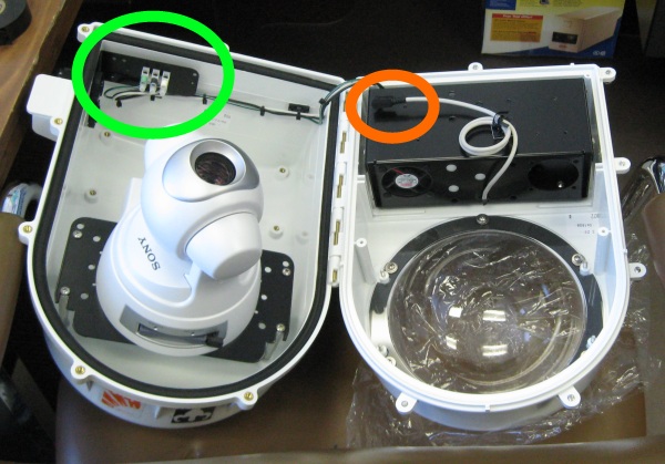
Enclosure interior

Enclosure interior

The enclosure also came with a magic universal mounting bracket and stand-offs of various heights to ensure you can position a compatible webcam at the right height to see out the bottom dome.
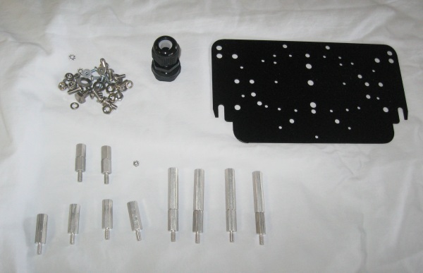
Mounting plate stand offs

Mounting plate stand offs

Here is a picture of the connectors on the back of the webcam:

Sony back

Sony back

We attached the camera as high as we could and still reach it with a scissor lift that facilities owns. The first time we installed the enclosure, we had it mounted by the pole climbers that were doing maintenance on the antennas at the top of the tower (no way I could ever do that – waaayyy too high up). We relied on the seal built into the enclosure to handle sealing out the moisture, but unfortunately it slowly started amassing some moisture inside which started pooling up inside the dome over several months. Since we didn’t have the requisite climbing gear to climb the tower, we ended up having the tower climbers move the enclosure down the pole just high enough for us to reach with the scissor lift when they came back again. We didn’t take any chances this time. We went along the exterior seam and penetrations with some marine RTV (silicone sealant) and I used some velcro tape to secure a plastic container filled with desiccant packs on top of the black mounting plate to keep the inside as dry as possible. The velcro would keep any tower vibrations from storms and the like from working the desiccant packs over the edge and down onto the dome.

Webcam on tower

Webcam on tower

We made sure to loop some additional network and power cable up the tower just in case we needed to move the enclosure to a different height or to another side of the tower. Make sure to make a “drip loop” with any cables that dips down from the enclosure and then back up away from it. This keeps water from flowing down the cable and running against the penetration, thus minimizing the likelihood of water making its way into the housing. Remember that the cables are exposed to the elements, which includes ultraviolet radiation (UV from sunlight) which can break down most plastics and vinyl cable sheathing. We selected an extension cord which listed UV resistance and selected an outdoor network cable to stave off the UV damage to the cables.
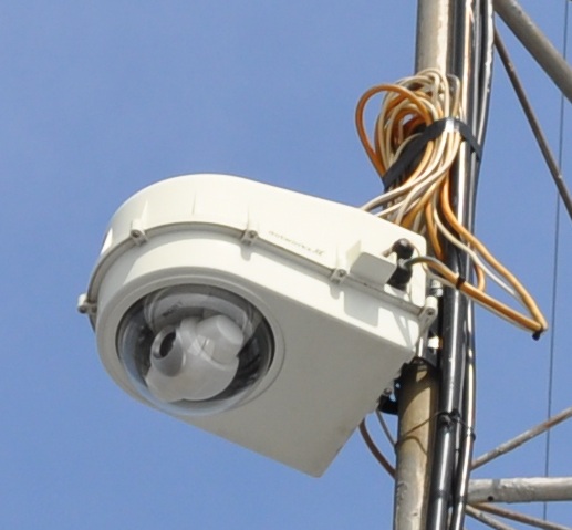
Webcam on tower closeup

Webcam on tower closeup

One last treatment I did was to apply Rain-X to the outside of the dome. It’s like a wax coating for glass that makes water bead up and roll down the dome rather than stick to the outside and fog up your view.

WebcamXP

One last topic I’d like to cover is the use of WebcamXP as a bridge between the webcam and the outside world. The problem with most webcams is that of security and scale. The internal web server in most webcams can handle about 25-50 simultaneous users. If you have more than that number, attempts to view the feed by users 51 and up will fail. To overcome this limitation, we purchased WebcamXP as an intermediary. The software installs on a desktop or server and it makes a connection to the webcam and handles the task of streaming it to the web server that you’re embedding the feed on. By acting as the intermediary, WebcamXP offloads the streaming load from the webcam. In our case we embed a Flash SWF file on the external webserver that gets its stream from WebcamXP.

The second issue that you run into with many webcams is that of security. They have some basic security built-in, but in order to stream the video from many of them, you have to expose the ability to control and position the webcam to the end-user. The last thing we wanted was for random users repositioning the webcam. Our solution was to give the webcam an internal IP address that was not accessible from outside our border routers. The system running WebcamXP was given a publicly accessible IP address and an internal IP address so that it could access the webcam video stream and serve it up externally.

Other nice features of the software are:

  • Watermarks – the software allows you to embed a watermark image over your video stream, thus branding your video with your logo and/or text.
  • Ability to expose the video stream via Java, Javascript or a Flash client.
  • Ability to handle multiple IP webcams simultaneously. If you want to grow the number of webcams you want to expose, you would only need one system running WebcamXP to stream the feeds from multiple webcams simultaneously.
  • A free version, which can handle a single webcam. This allows you to kick the tires and make sure the software does what you want before you buy. (Note, the free version does not allow watermarking your logo on the video stream)

I had initially looked into using either Silverlight and/or the IIS Streaming Server to handle this roll, but it was early in their development when we set the webcam up and it was more expedient to use WebcamXP. I’d still like to look into having our actual web server do the work of connecting to the internal webcam and handle streaming the content using Silverlight or some other non-Flash mechanism. If you have some feedback as to how to accomplish this, I’m all ears. I think it would make a much more flexible mechanism to handle the various browsers (including mobile, iPad etc.) that are coming online.

Thanks for enduring the long post and please feel free to comment if you can think of things I missed or have any suggestions on how to improve things.

Time Lapse Video on the Cheap

The video above is a time lapse of a day in the life of the UD Wind Turbine in Lewes, Delaware.

We were quite excited when they told us that the UD Wind Turbine project was a go. As the time grew near for construction to start, we wanted to chronicle the construction progress and create a time lapse video. I did some research and looked into various webcams with weatherproof housings and the like, but sticker shock at the multi-thousand dollar price tags for the equipment, as well as the networking and power hassles to connect to it made me shy away from a complicated rig. I decided that the best way to go is the simple route.

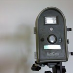
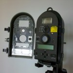
The task really screamed for a lower cost, battery powered, weather-resistant camera that could be set to take a picture every X number of minutes. I finally narrowed the search down to Wingscapes Birdcam 2.0 outdoor camera. The camera retails for about $200 but I found it on Amazon for just over $150. It has lots of advanced features like motion sensing, light sensing, has a built-in flash plus lots of other nifty features. The main selling points for me were that it was designed for outside use (the turbine was being installed in Spring and it was rainy), it stored its images on an easily accessible secure digital card (up to 4Gigs), it had a user programmable time lapse mode, and it ran on four D-cell batteries for > 4 weeks worth of endurance.

As you can see from the time lapse video that MPEO created of the construction at the turbine base, the results were just what we were looking for (except for the big pile of dirt they put in front of the camera ;?). The video from afar was created using images FTP’d from a webcam located over at the Marine Operations Building. I’ll cover the configuration and components for that webcam setup in a later posting.

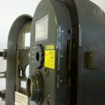
I can easily imagine many other uses for this kind device. Time lapse videos of coastal erosion, tide cycles, lab experiment time series, etc. In addition to the features cited above, the camera also has a video and a USB output on the side of the unit as well as an external power connector at the bottom for more lengthy time lapses. All-in-all, highly recommended.

Birdcam Cover Closed

Cover Closed

Birdcam with the cover open

Cover Open

Birdcam Side View

Side View

I used iMovie to create the movie at the top from all of the stills for this post, but I also just as easily created one using the freely downloadable Windows Live Movie Maker if you’re running Windows.

Polar Orbiting Satellite Receiving Station

The video above is a quick screencast NASA JPL’s Eyes on the Earth application, which shows the tracks of various satellites orbiting the globe. It’s a really cool application that gives a top-notch overview of some of the satellites currently in orbit and their trajectories around the Earth. Take some time and poke around, you’ll be glad you did.

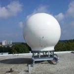
Polar Satellite RadomeThe reason I included it is that I promised to cover the polar orbiting satellite receiving station in a previous blog post about the new Satellite Receiving Station in Delaware. In the previous post I discussed the geostationary satellite receiving station. In this post, I hope to shed some light on the polar orbiting receiving setup.

What’s Inside the Radome

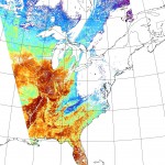
MODIS Satellite PassThe equipment for the polar orbiting satellite receiving station is a bit more involved than the pretty much non-moving geostationary setup. As the name implies, the polar orbiting satellites do just that, they orbit the Earth north and south, going from pole to pole. Their path is relatively simple, they just go around the earth in circles, but as they’re doing so, the Earth is rotating beneath them. The satellites point their cameras towards the earth and essentially capture a swath of data during each rotation. Since the Earth is rotating beneath them, the swath appears as a diagonal path if you look at the overlay.

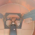
Inside the RadomeIn order to capture data from a moving target, the dish has to be able to rotate and move in three axis in order to follow the satellite of interest. In order to protect the receiving equipment from the weather, it is typically installed in a circular fiberglass enclosure called a “radome”. To keep the design relatively simple, there is only one mounting configuration and radome setup created, and that’s designed to mount onboard a ship. It is then relatively simple to attach a mounting bracket to the top of a building and bolt the radome assemgly to it.

The video at the top of the page shows that there are several satellites in orbit, so the Terascan software has to pull down satellite ephemeral data from Celestrak each day, take into account the location of the tracking station, and generate a calculated schedule of which satellites will be visible to the satellite dish throughout the day. As there may be more than one satellite in view during any given time period, the satellite operator assigns a priority weighting to each satellite. The Terascan software then uses that weighting to decide which satellite it will aim the dish at and start capturing data.

Receiving Station Workstations

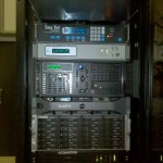
Acquisition and Processing SystemsInside the building is a rack of computers and receivers whose purpose in life is to control the dish on the roof of the building and to receive and process the data it relays down from the satellite. The receiving station at UD has both X and L-Band receivers which receive the data stream and pass it to a SeaSpace Satellite Acquisition Processor. The processor then sends the data packets to a Rapid Modis Processing System (RaMPS) which combines the granularized HDF data files from the satellites into a TeraScan Data File (TDF) file. Once in this format, various programs and algorithms can be run against the TDF file and channels of interest can be combined using NASA/NOAA and other user supplied algorithms to create the output product of interest. As the files can get rather large and there can be several of them coming in throughout the day, they are then moved over to a Networked Attached Storage (NAS) server and stored until they are needed.

Satellites Licensed

The UD receiving station is licensed and configured to receive data from the following satellites:

  • Aqua
  • Terra
  • NOAA 15
  • NOAA 17
  • NOAA 18
  • NOAA 19
  • MetOp-A (Europe)
  • FY-1D (China)

Hopefully this sheds a little more light on the polar orbiting receiving station and its capabilities. Let me know if there are any additions or corrections to the information I’ve posted.

REU Intern on FIRe

It has been a great pleasure to have Lauren Wiesebron on the Lewes campus this summer. Lauren is a summer intern from Johns Hopkins and is here as part of an NSF funded Research Education for Undergraduates program (aka REU). For her summer project, Lauren worked in Dr. Matt Oliver’s lab (the ORB Lab) and chose “photosynthetic efficiency” as her summer research project.  To gather data for her project, she set up shop in a portable scientific lab van on the dock in which she set up a Fluorescence Induction and Relaxation System (FIRe Sensor), a Coulter Counter and a Submersible Ultraviolet Nitrate Analyzer (SUNA).  Dr. George Luther’s lab was also taking readings from the same lab van and Lauren included some of their data into her analysis.  The past few weeks Lauren analyzed the results and tomorrow she will present a talk called “Conditions for increased photosynthetic efficiency in an estuarine area”.  Here is a walk-through of the lab van that I did earlier this week with Lauren.

Excellent work Lauren and we hope to see you back here for Grad school!

© 2024 Ocean Bytes Blog

Theme by Anders NorenUp ↑